SMB/SMC Series
Specifications
Electrical:
SMB
|
Impedance |
50 ohm |
|
|
|
0 - 4 GHz |
|
|
Working Voltage |
RG-178:250 VRMS max. RG-316,.085” :335 VRMS max. |
|
|
Dielectric Withstanding Voltage |
RG-178:750 VRMS min. RG-316,.085” :1000 VRMS min. |
|
|
VSWR
|
Straight |
1.3 Max. |
|
Right Angle |
1.5 Max. |
|
|
Contact Resistance |
Center Contact |
6 Milliohms Max. |
|
Outer Contact |
2.5 Milliohms Max. |
|
|
Insulator Resistance |
1000 Megohms min. |
|
SMC
|
Impedance |
50 ohm |
|
|
|
0 - 10 GHz |
|
|
Working Voltage |
RG-178:250 VRMS max. RG-316,.085” :335 VRMS max. |
|
|
Dielectric Withstanding Voltage |
RG-178:750 VRMS min. RG-316,.085” :1000 VRMS min. |
|
|
VSWR |
Straight |
1.3 max. |
|
Right Angle |
1.5 max. |
|
|
Contact Resistance |
Center Contact |
6 Milliohms Max. |
|
Outer Contact |
2.5 Milliohms Max. |
|
|
Insulator Resistance |
1000 Megohms min. |
|
Material:
|
Parts
Name |
Material |
Finish |
|
Body, Metal Parts |
Brass per QQ-B-626 |
Nickel or Gold per requirement |
|
Center Contacts |
Plug: Brass per QQ-B-626 |
Gold |
|
Jack: Beryllium copper per QQ-B-530 |
Gold |
|
|
Insulators |
Teflon |
None |
|
Crimp Ferrules |
Annealed copper |
Nickel or Gold per requirement |
|
Clamp Gaskets |
Silicone rubber |
None |
NOTE:Other Material/Finish is Available on Request.
Mechanical
& Environmental:
SMB
SMC
|
Engagement Force |
8 lbs. max. |
16 in-ozs. max. |
|
Disengagement Force |
8 lbs. min. |
16 in-ozs. max. |
|
Coupling Nut Retention |
Not applicable |
35 lbs.min. |
|
Coupling Proof Torque |
Not applicable |
100 in-ozs. |
|
Contact Retention |
4 lbs. min. |
4 lbs. min. |
|
Durability(Mating) |
500 cycles min. (for Beryllium copper Jack contact only) |
500 cycles min.(for Beryllium copper Jack contact only) |
|
|
-65°C to 165°C |
|
|
Vibration |
MIL-STD-202 Method 204 Test Cond.B. |
|
|
Salt Spray |
MIL-STD-202 Method 101 Test Cond.B. |
|
|
Thermal Shock |
MIL-STD-202 Method 107 Test Cond.B. |
|
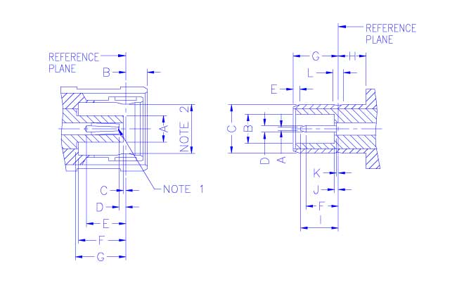
INTERFACE MATING
DIMENSIONS(SMB)
|
PLUG |
|
|
JACK |
||||
|
Letter |
Millimeters |
|
|
Letter |
Millimeters |
||
|
Minimum |
Maximum |
|
|
Minimum |
Maximum |
||
|
A |
2.00 |
2.06 |
|
|
A |
- |
0.25 |
|
B |
- |
1.62 |
|
|
B |
2.08 |
2.16 |
|
C |
0.18 |
- |
|
|
C |
3.66 |
3.71 |
|
D |
0.18 |
0.94 |
|
|
D |
0.48 |
0.53 |
|
E |
2.97 |
- |
|
|
E |
0.00 |
- |
|
F |
3.58 |
- |
|
|
F |
1.32 |
- |
|
G |
3.58 |
- |
|
|
G |
3.33 |
3.58 |
|
|
|
|
|
|
H |
2.03 |
- |
|
|
|
|
|
|
I |
- |
2.97 |
|
|
|
|
|
|
J |
- |
0.18 |
|
|
|
|
|
|
K |
- |
0.18 |
|
|
|
|
|
|
L |
0.69 |
0.94 |
NOTE
1:I.D. TO MEET VSWR AND CONTACT RESISTANCE
WHEN MATED WITH 0.48/0.53 MM DIA. PIN.
NOTE
2:MUST MEET THE FORCE TO ENGAGE AND DISENGAGE
WHEN MATED WITH MATING PART.
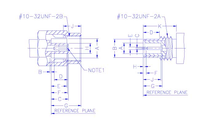
INTERFACE MATING
DIMENSIONS(SMC)
|
PLUG |
|
|
JACK |
||||
|
Letter |
Millimeters |
|
|
Letter |
Millimeters |
||
|
Minimum |
Maximum |
|
|
Minimum |
Maximum |
||
|
A |
3.73 |
3.81 |
|
|
A |
2.08 |
2.16 |
|
B |
0.00 |
0.30 |
|
|
B |
3.63 |
3.71 |
|
C |
3.15 |
3.40 |
|
|
C |
- |
0.25 |
|
D |
2.79 |
- |
|
|
D |
3.12 |
3.83 |
|
E |
- |
3.10 |
|
|
E |
0.48 |
0.53 |
|
F |
3.05 |
3.40 |
|
|
F |
0.61 |
- |
|
G |
- |
5.92 |
|
|
G |
3.40 |
3.76 |
|
H |
2.00 |
2.06 |
|
|
H |
0.00 |
0.30 |
|
J |
2.79 |
- |
|
|
J |
3.40 |
3.66 |
|
|
|
|
|
|
K |
5.94 |
- |
NOTE
1:I.D. TO MEET VSWR AND CONTACT RESISTANCE
WHEN MATED WITH 0.48/0.53 MM DIA. PIN.