MCX Series
Specifications
Electrical:
|
Impedance |
50 ohm |
||
|
|
0 - 6 GHz |
||
|
Working Voltage |
335 VRMS max. |
||
|
Dielectric Withstanding Voltage |
1000 VRMS min. |
||
|
VSWR |
Straight |
1.3 max |
|
|
Right Angle |
1.5 max |
||
|
Contact Resistance |
Center Contact |
5 Milliohms Max. |
|
|
Outer Contact |
2.5 Milliohms Max. |
||
|
Insulator Resistance |
1000 Megohms min. |
||
Material:
|
Parts
Name |
Material |
Finish |
|
Body, Metal Parts |
Brass per QQ-B-626 |
Nickel or Gold per requirement |
|
Center Contacts |
Plug: Brass per QQ-B-626 |
Gold |
|
Jack: Beryllium copper per QQ-C-530 |
Gold |
|
|
Insulators |
Teflon |
None |
|
Outer Contact of male |
Beryllium copper per QQ-C-530 |
Gold |
|
Crimp Ferrules |
Annealed copper |
Nickel or Gold per requirement |
NOTE:Other Material/Finish is Available on Request.
Mechanical
& Environmental:
|
Engagement Force |
3.4 lbs. max. |
|
Disengagement Force |
4.5 lbs. max. |
|
Contact Retention |
4 lbs. min. |
|
Durability(Mating) |
500 cycles min.(for Beryllium copper jack contact only) |
|
|
-65°C thru 155°C |
Vibration
|
3 cycles, 3 opposite directions, 10-150 Hz, 10-60 Hz: 0.75mm/.030 in., 60-150Hz 10G’s |
Temperature Shock
|
MIL-STD-202 Method 107 |
Humidity
|
MIL-STD-202 Method 103, Condition B. |
Mechanical Shock
|
MIL-STD-202 Method 213, Condition B. |
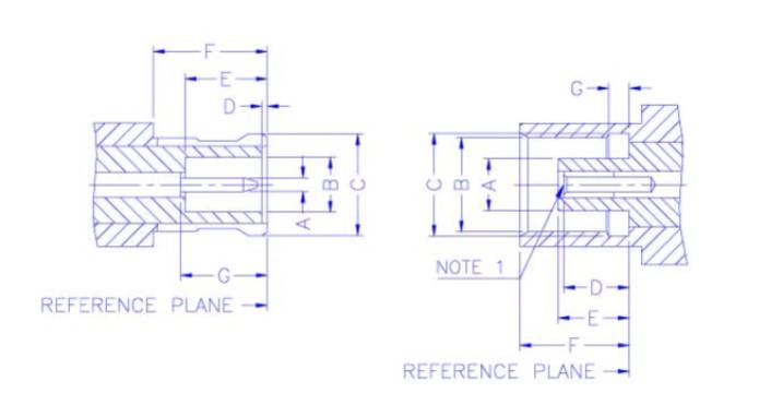
INTERFACE MATING DIMENSIONS
|
PLUG |
|
|
JACK |
||||
|
Letter |
Millimeters |
|
|
Letter |
Millimeters |
||
|
Minimum |
Maximum |
|
|
Minimum |
Maximum |
||
|
A |
0.48 |
0.53 |
|
|
A |
1.80 |
1.97 |
|
B |
2.00 |
2.07 |
|
|
B |
3.43 |
3.48 |
|
C |
3.66 |
3.76 |
|
|
C |
3.61 |
3.75 |
|
D |
0.00 |
0.30 |
|
|
D |
2.31 |
2.79 |
|
E |
2.81 |
3.20 |
|
|
E |
2.61 |
2.79 |
|
F |
4.16 |
- |
|
|
F |
4.00 |
4.12 |
|
G |
2.81 |
3.20 |
|
|
G |
0.75 |
0.85 |
|
|
|
|
|
|
|
|
|
NOTE
1:I.D. TO MEET VSWR AND CONTACT RESISTANCE
WHEN MATED WITH 0.48/0.53 MM DIA. PIN.