BT43 Series
Specifications
Type 43
series-features:
Proven
design
Where applicable the Type 43 product range is
approved to all current BT specifications, as well as
being the first choice
for many other new or existing analogue or digital telecommunication system
e.g.
land based, mobile, PCN and GSM networks.
Low cost
Low installation cost due to high quality, proven crimp center
contact design.
High
performance
Excellent VSWR at rated frequencies up to
5GHz.
Reliable
Long life design, incorporating special locking feature which
prevents accidental disconnection apple.
Fast
termination
Single piece body styles allow reliable,
easy operator assembly in varied on-site condition.
Electrical:
|
Impedance |
75 ohm | ||
|
|
0-3 GHz | ||
|
Working Voltage |
500 VRMS max. | ||
|
Dielectric Withstanding Voltage |
1500 VRMS min. | ||
|
VSWR |
Straight |
1.3 max | |
|
Right Angle |
1.5 max | ||
|
Contact Resistance |
Center Contact |
5 Milliohms Max. | |
|
Outer Contact |
2 Milliohms Max. | ||
|
Insulator Resistance |
5000 Megohms min. | ||
Material:
|
Parts Name |
Material |
Finish |
|
Body, Metal Parts |
Brass per QQ-B-626 |
Nickel or Gold per requirement |
|
Center Contacts |
Plug: Brass per QQ-B-626 |
Nickel or Gold per requirement |
|
Jack: Beryllium copper per QQ-C-530 or Phosphor Bronze per QQ-B-750 |
Nickel or Gold per requirement | |
|
Insulators |
Teflon |
None |
|
Outer contact of Plug |
Beryllium copper per QQ-C-530 or Phosphor Bronze per QQ-B-750 |
Gold |
|
Crimp Ferrules |
Annealed copper |
Nickel or Gold per requirement |
|
Panel Grommet |
Polyacetal |
None |
|
Panel Mounting Hardware |
Brass or Phosphor Bronze |
Nickel or Gold per requirement |
*In general all Type 43
series connector bodies are gold plated in mating areas
Mechanical &
Environmental:
|
Mechanical endurance |
250 matings |
|
Cable Retention (Plug Connectors) |
220 N min. |
|
Cable Retention (Socket Connectors) |
220 N min. |
|
Center Contact Retention (Plug Connectors) |
22 N min. |
|
Center Contact Retention (Socket Connectors) |
22 N min. |
|
Weight |
10g (grams) typical |
|
|
-40°C to 100°C |
Vibration |
MIL-STD-202 Method 204 Test Cond.B. |
Salt
Spray |
MIL-STD-202 Method 101 Test Cond.B. |
Thermal
Shock |
MIL-STD-202 Method 107 Test Cond.B. |
INTERFACE MATING
DIMENSIONS
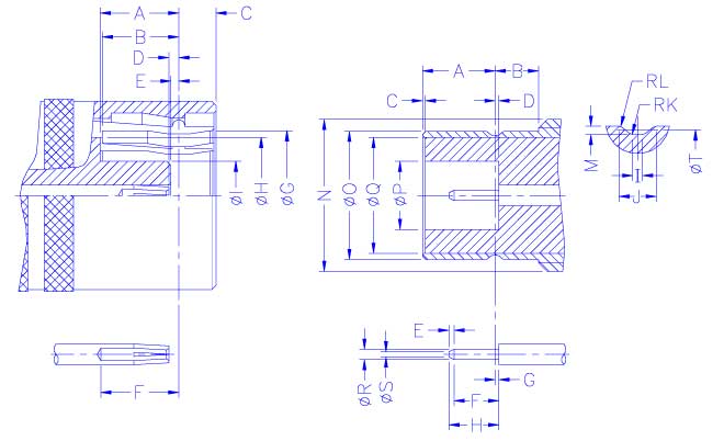
|
PLUG |
|
|
JACK | ||||
|
Letter |
Millimeters |
|
|
Letter |
Millimeters | ||
|
Minimum |
Maximum |
|
|
Minimum |
Maximum | ||
|
A |
3.63 |
3.83 |
|
|
A |
3.33 |
3.58 |
|
B |
3.61 |
3.77 |
|
|
B |
2.01 |
- |
|
C |
- |
1.8 |
|
|
C |
0.00 |
- |
|
D |
0.23 |
0.38 |
|
|
D |
- |
0.18 |
|
E |
0.23 |
0.48 |
|
|
E |
0.25 |
- |
|
F |
3.2 |
3.53 |
|
|
F |
1.32 |
- |
|
ØG |
6.25 |
- |
|
|
G |
- |
0.18 |
|
ØH |
5.60
NOM |
|
|
H |
- |
2.97 | |
|
ØI |
- |
3.33 |
|
|
I |
0.28 |
0.38 |
|
|
|
|
|
|
J |
0.69 |
0.94 |
|
|
|
|
|
|
RK |
- |
0.13 |
|
|
|
|
|
|
RL |
0.05 |
0.15 |
|
|
|
|
|
|
M |
0.15 |
0.25 |
|
|
|
|
|
|
N |
- |
7.94 |
|
|
|
|
|
|
ØO |
6.20 |
6.25 |
|
|
|
|
|
|
ØP |
3.35 |
- |
|
|
|
|
|
|
ØQ |
5.60
NOM | |
|
|
|
|
|
|
ØR |
0.48 |
0.53 |
|
|
|
|
|
|
ØS |
- |
0.25 |
|
|
|
|
|
|
ØT |
5.97 |
6.07 |